Skip to content
BlackOwl GPS
GPS Trackers
GPS Trackers
OBD2
Hardwired
Portable (Small)
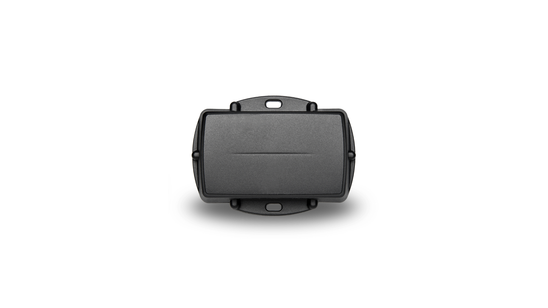
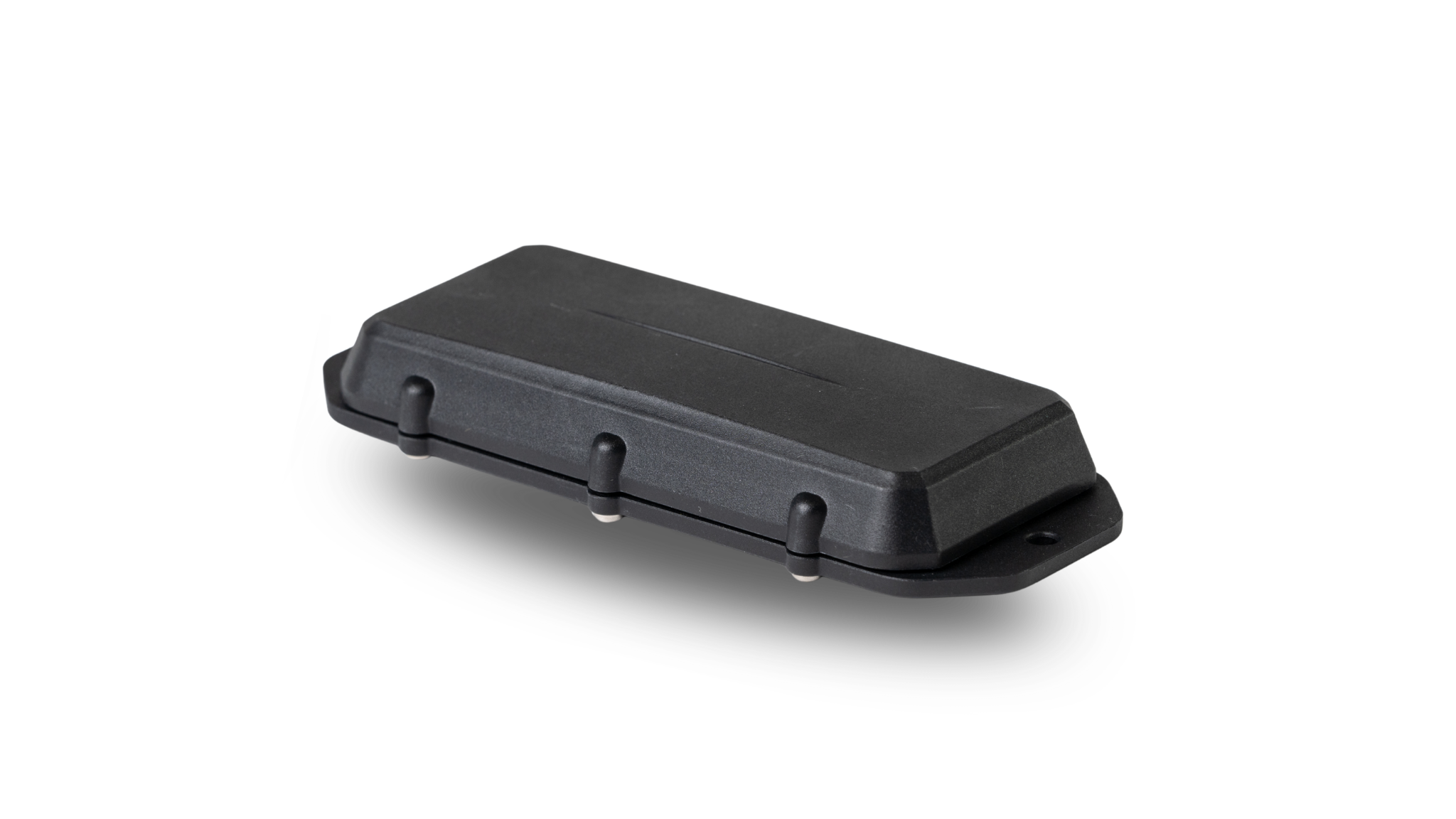
Portable (Large)
Accessories
Accessories
OBD2 Extension Cable
Hardwired > OBD2 Adapter
Hardwired > Cigarette Adapter
Pricing
Free Trial
FAQ
Client Hub
About
About
About Us
Contact
Facebook
Instagram
BlackOwl GPS
GPS Trackers
OBD2
Hardwired
Portable (Small)
Portable (Large)
Accessories
OBD2 Extension Cable
Hardwired > OBD2 Adapter
Hardwired > Cigarette Adapter
Pricing
Free Trial
FAQ
Client Hub
About
About Us
Contact
Enquire now
03 9111 6969
Search
Search
Cart
User guide
Installation
OBD2
View
Hardwired
View
Portable Small
View
Portable Large
View
Cart
0
There’s nothing in your cart yet
Start Shopping
Loading...
Choosing a selection results in a full page refresh.